Can a team-designed locomotive bogie be independently validated component-by-component, manufactured to schedule, and brought into compliance with the Institution of Mechanical Engineers' mandatory physical envelope — all before a fixed competition deadline?
The IMechE Railway Challenge is a genuine systems-engineering competition: 8 team members across mechanical, electrical, and controls disciplines had to design, manufacture, and race a real locomotive against international university teams at Stapleford Miniature Railway — sponsored by industry partners who expected a working machine, not just a design study. Every structural component has to survive real dynamic loads, and the whole vehicle must physically fit within a strict regulatory envelope before it's even allowed to compete. There's no partial credit for a locomotive that doesn't fit the track or fails on the day.
- Validated 18 mechanical and 2 electrical components within the bogie and unsprung assembly by hand-calculating safety factors — achieving a minimum safety factor of 1.83 on the critical shaft, up to 16.5 on the wheel-axle friction coupling
- Created design specifications for newly designed components — the traction centre, anti-roll bar, and bogie top plate — by calculating their operating forces, constraints, and clearances from first principles
- Defined all six degrees of freedom (shuttle, roll, lurching, pitch, bouncing, yaw) between wheelset, bogie, and body, then calculated both the unconstrained displacement each would see with no restraint and the constrained displacement once every suspension element was in place — the figure directly below this bullet — enabling correct selection of the rubber bushings, axle box T-bars, anti-roll bar, bump-stops, and traction centre hooks throughout
- Co-led the locomotive's compliance with IMechE's mandatory Dynamic Loading Gauge (DLG) — completing the required DLG, battery, and power calculations ahead of competition entry
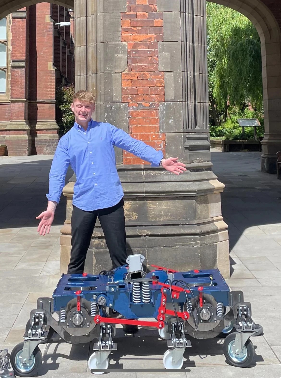
- Took charge of manufacturing the entire unsprung assembly (every component except the belt drive), the steering links, the traction centre, and all bushing couplings
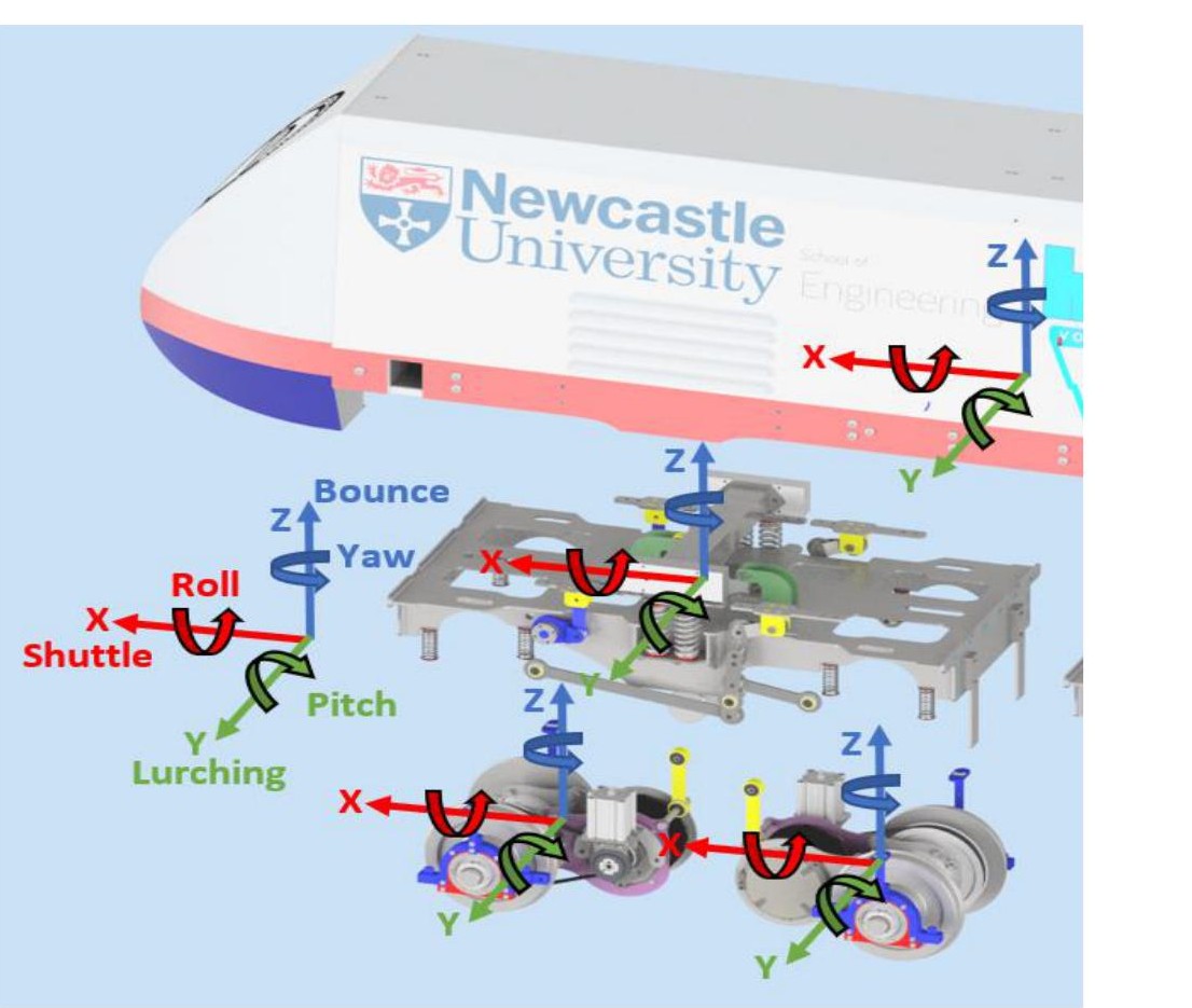
This mattered because none of those six motions are independent: constrain roll too tightly with the anti-roll bar and there's no travel left to absorb track twist; leave yaw too free at the bogie-body interface and the locomotive's body swings excessively into corners. Working from first principles, I calculated the deflection each interface needed under both regimes — for example, roll between wheelset and bogie needed 11.5° unconstrained down to 0.439° once the axle box T-bar was sized correctly — and used that pairing of numbers, not just the axle box T-bar name, to size and specify every bushing, spring, and hook in the bogie.
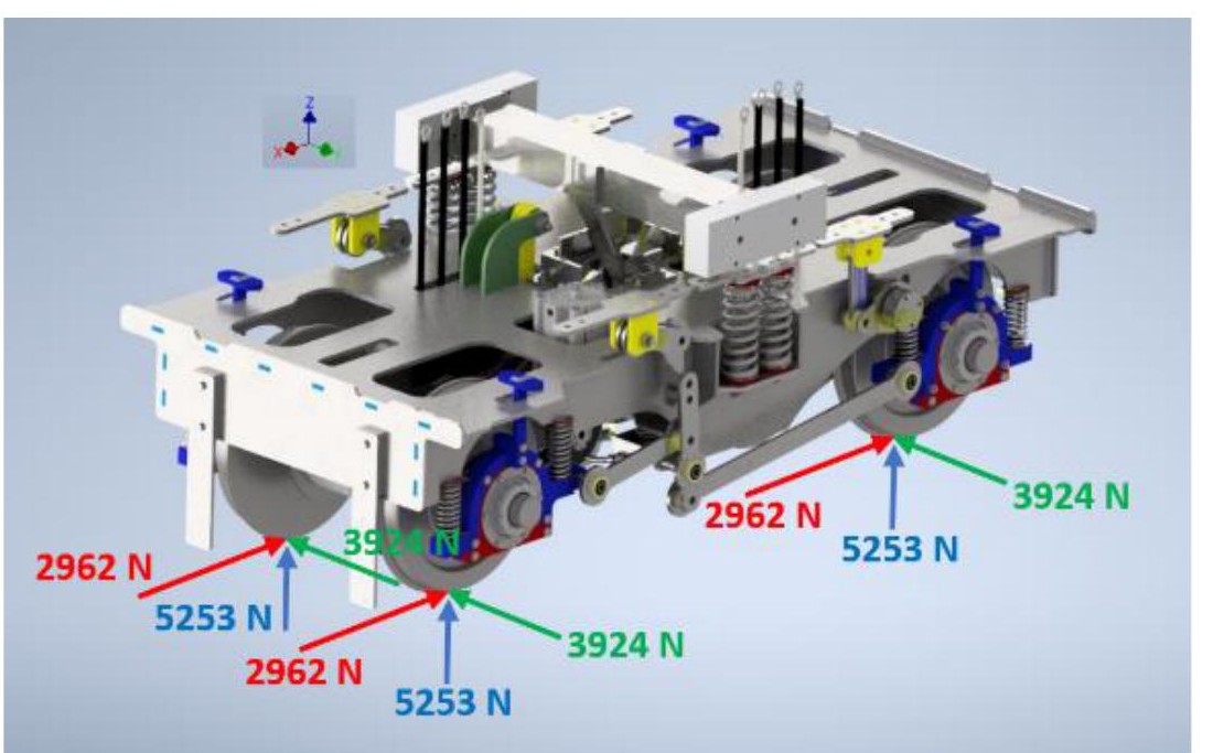
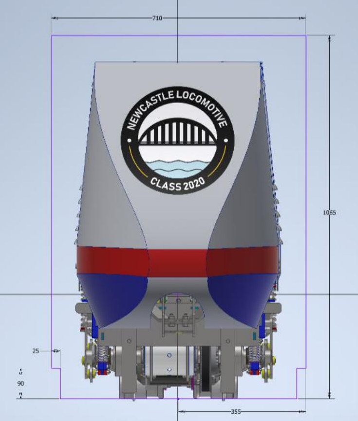
Every friction coupling in the locomotive was validated with a safety factor above 2.8 (up to 16.5 on the wheel-axle coupling), and after redesigning the anti-roll bar and tightening suspension travel limits, the locomotive fit within its mandatory dynamic envelope with 26.9mm of clearance at the roof and 6.5mm at its widest point — comfortably compliant, but with margins tight enough that every earlier calculation genuinely mattered.
This was hands-on systems engineering under a fixed, external deadline: validating real components against calculated loads, then personally manufacturing the assemblies those calculations were for — with no opportunity to redo a physical part once it existed. That same discipline — calculate, validate, build, and verify the finished hardware actually complies with the requirement — carried directly into designing, manufacturing, and commissioning the custom wind tunnel used throughout the DPhil's experimental work.