Does the flow environment a surface heat exchanger is actually installed in — rather than the simplified uniform flow typically assumed during design — change its aerodynamic and thermal performance?
Surface heat exchangers of this type — a flat plate with internal fluid channels and fins protruding into the external flow — are used across many applications beyond this liquid hydrogen heat exchanger, including surface air-cooled oil coolers and heat sinks for electric propulsion. In every case, they're typically installed downstream of an outlet guide vane row, where the flow is spatially non-uniform rather than the clean, uniform flow most design correlations assume. Out of the two heat exchanger geometries sized in Stage 1, this conventional design was selected for this deep-dive as the most novel and highest-value component in the architecture — the physical wind tunnel is used to test this conventional geometry directly, providing the ground-truth dataset that the CFD model in Stage 4 is validated against.
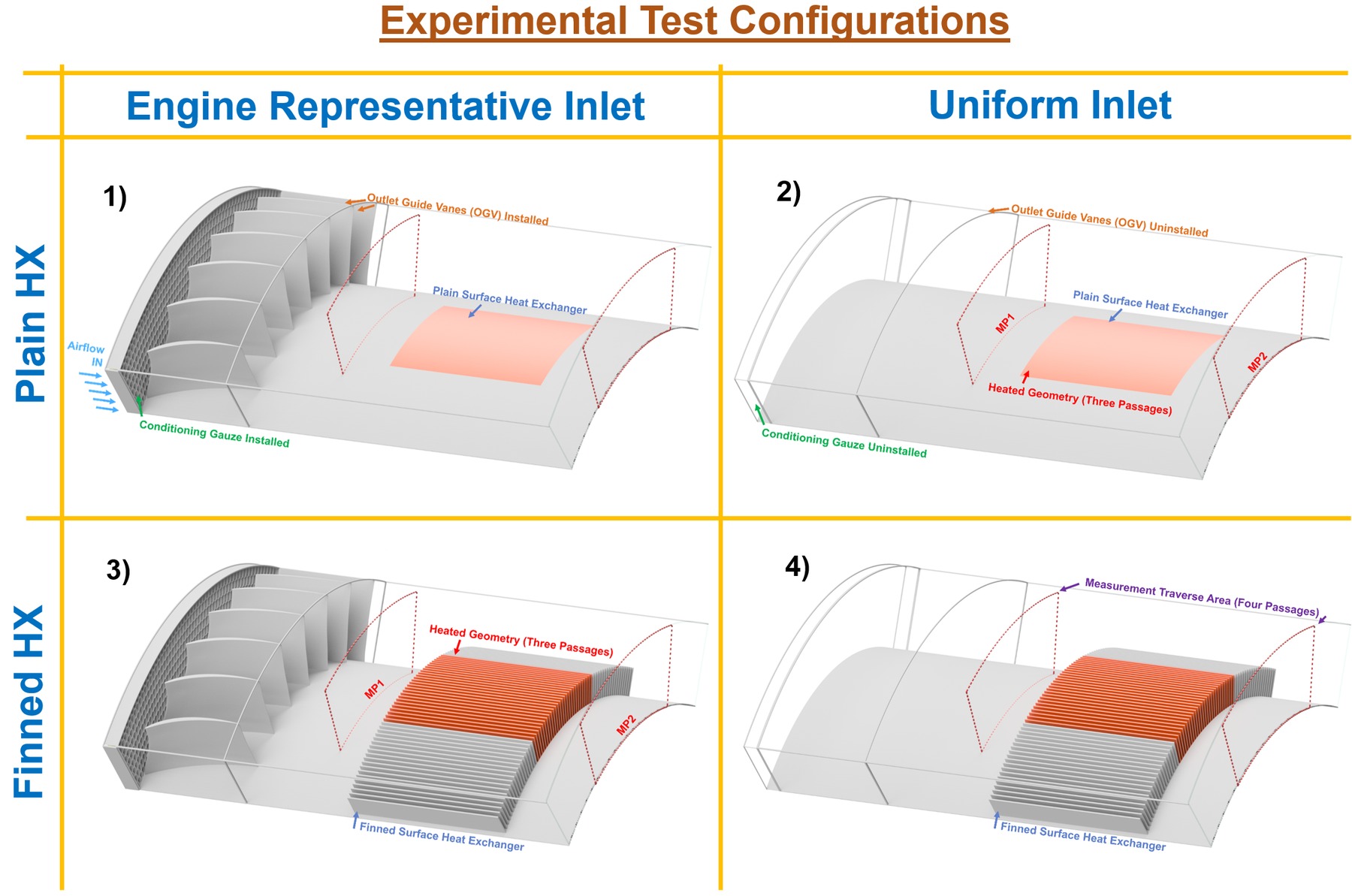
- Installed the conventional finned surface heat exchanger, alongside a plain fin-less reference geometry, in the hub of the modified annular wind tunnel's sector rig — four configurations in total, shown above
- Tested both geometries under two inlet conditions: a simple, collinear uniform flow with a thin boundary layer, and an engine-representative distorted flow generated by an upstream conditioning grid and outlet guide vane row, replicating the heat exchanger's real installation environment
- Measured aerodynamic loss and heat transfer performance across both geometries and both inlet conditions using pressure and thermocouple instrumentation and hotwire anemometry, with the heat exchanger surface held at a controlled temperature via closed-loop PID thermal control
- Identified the physical mechanisms driving any performance differences between uniform and distorted inlet flow
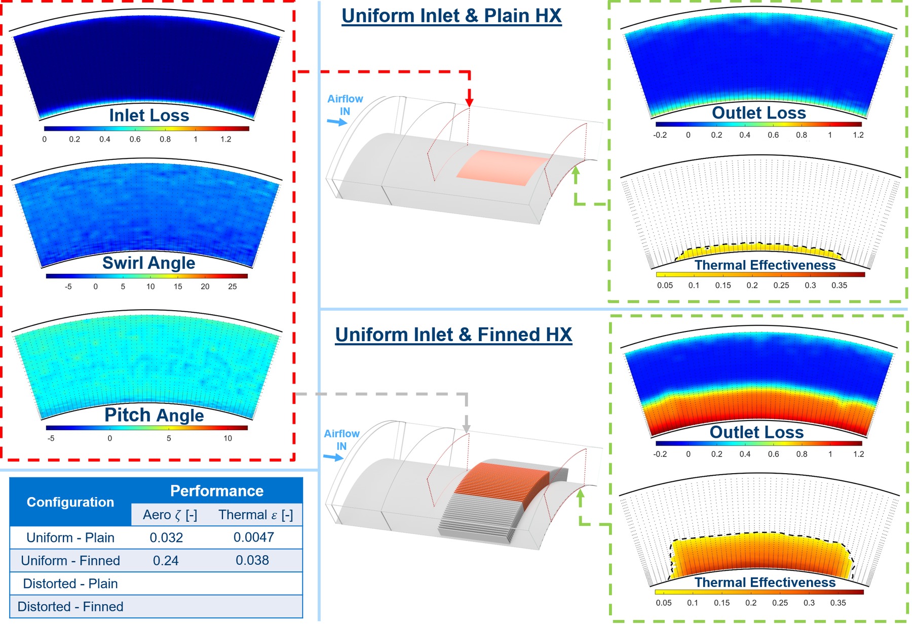
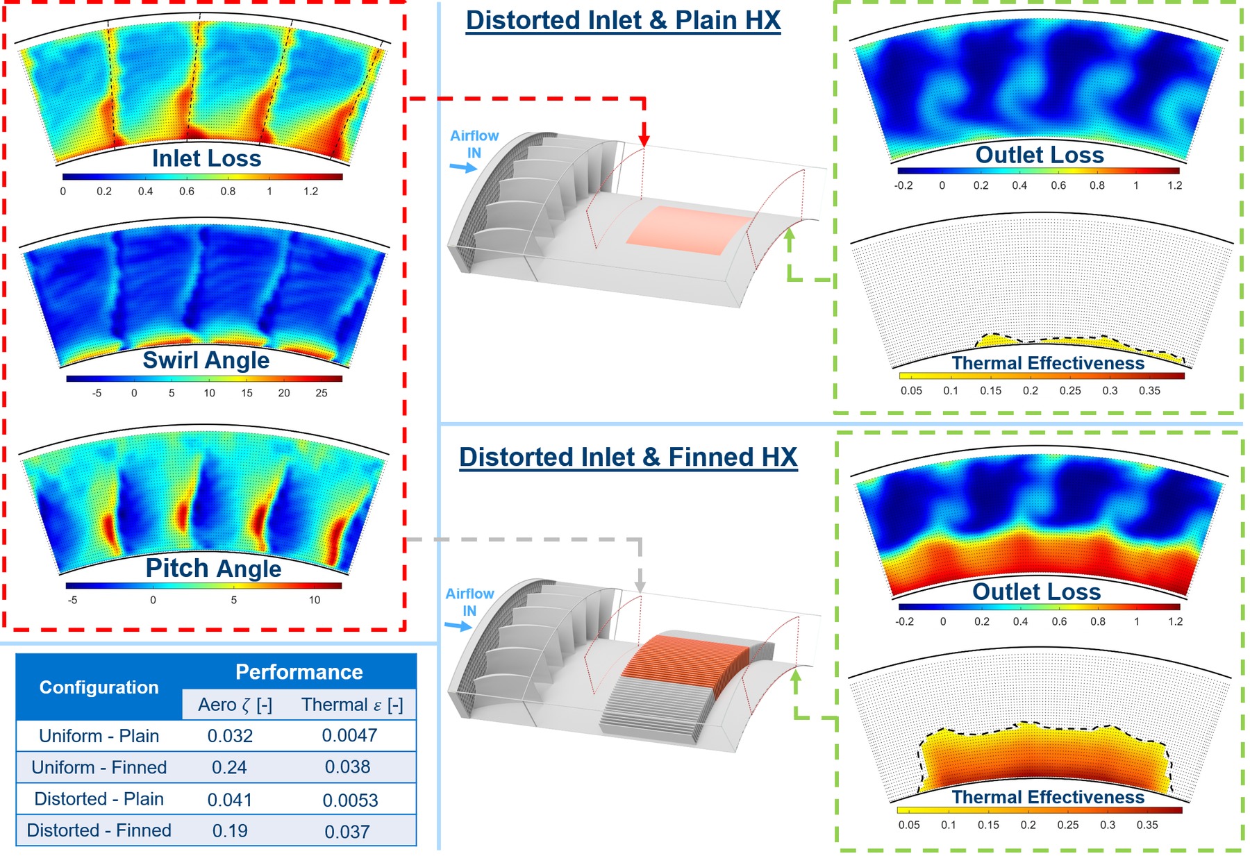
Installation-representative inlet distortion reduces aerodynamic loss for the finned geometry by over 20% (ζ = 0.24 uniform vs. 0.19 distorted), driven primarily by lower local velocities near the hub, while thermal effectiveness is maintained to within ~2% (ε = 0.038 uniform vs. 0.037 distorted) — the reduction in velocity being offset by additional heat transfer enhancement mechanisms (swirling endwall flow impingement, streamwise-vortex-driven mixing, and higher turbulence) under distorted inflow. This work formed the basis of a paper presented at the AIAA AVIATION Forum 2026 (see Publications), which concludes that installation-representative conditions cannot be neglected in the design and optimisation of surface heat exchangers.
These results demonstrated that installation-representative flow conditions cannot be neglected in surface heat exchanger design or optimisation — directly motivating the next stage, where this experimental dataset is used to validate a CFD model capable of exploring geometries far beyond what physical testing alone could cover.