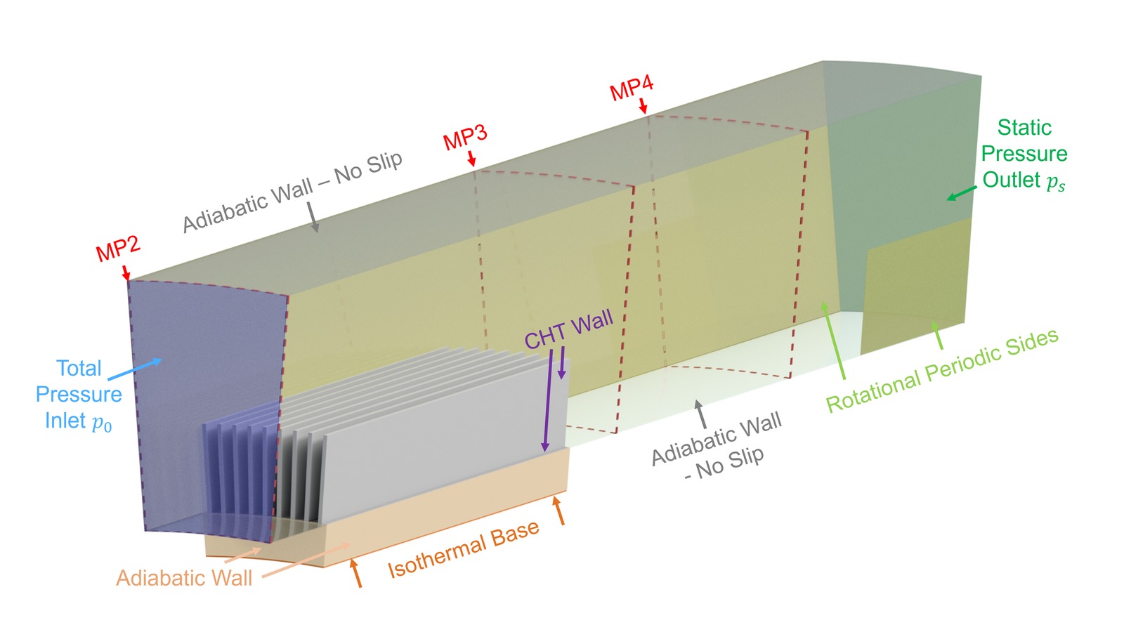
Can a CFD model of the surface heat exchanger and its installation environment be trusted to predict aerodynamic loss and heat transfer accurately enough to replace, rather than just supplement, physical testing during design optimisation?
Physical testing in the wind tunnel is essential for establishing ground truth, but it can't realistically explore the large design space needed to optimise a heat exchanger's geometry — every new fin height, spacing, or shape would mean a new physical test article. A validated CFD model removes that bottleneck, but only if it can be shown to reproduce the experimentally measured aerodynamic and thermal performance under both inlet conditions, not just one.
- Built a RANS CFD model of the annular sector rig, matching the geometry and boundary conditions of the wind tunnel test section
- Validated the CFD model's predicted aerodynamic loss and heat transfer against the Stage 3 experimental dataset, for both the finned and plain reference variants of the conventional geometry, under both uniform and distorted inlet conditions
- Investigated and resolved sources of discrepancy between CFD and experiment, including mesh sensitivity, turbulence model selection, and boundary condition definition
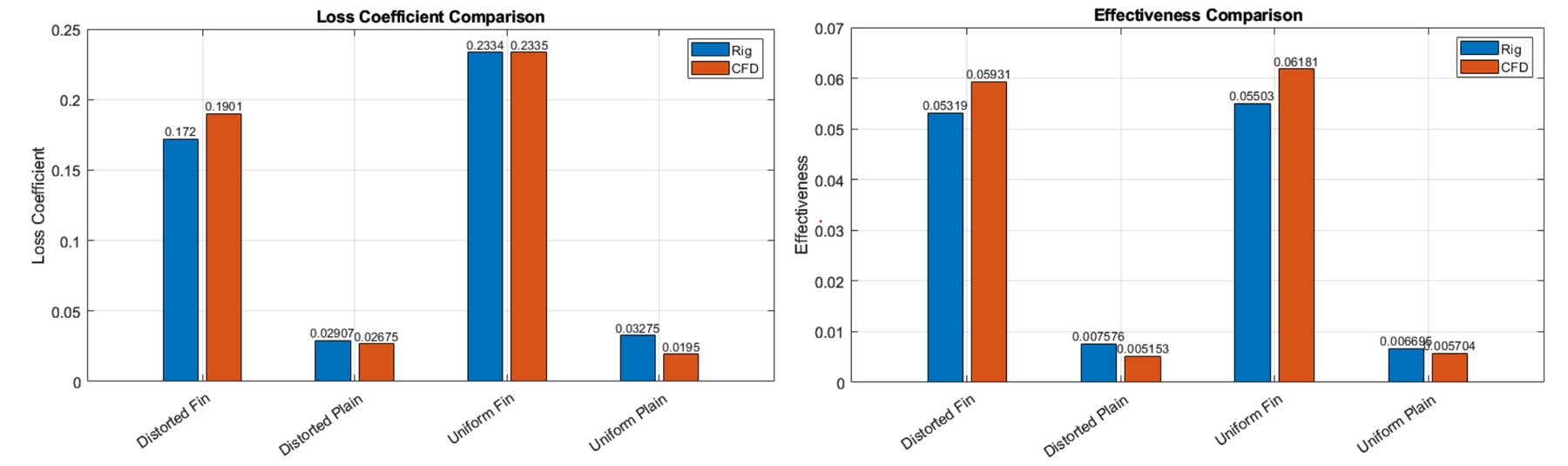
A CFD model validated against experimental data across both the finned and plain geometries and both inlet conditions, providing a trusted numerical tool capable of evaluating heat exchanger designs the wind tunnel could never practically test one-by-one.
With a validated CFD model in hand, the next stage uses it to drive a design-of-experiments campaign — exploring far more heat exchanger geometries than physical testing alone could ever reach, in search of an optimised design.