What would the thermal management architecture of a liquid hydrogen combustion jet engine actually look like — how many heat exchangers would it need, where would they be installed, and what fluids would be transferring heat between them?
Liquid hydrogen propulsion is one of the leading pathways to net-zero aviation, but burning hydrogen changes the engine's entire thermal balance: the fuel arrives cryogenic, needs substantial heat input before combustion, and the engine's conventional oil-cooling duties still have to be met. None of this can be designed in isolation — before any single heat exchanger can be sized, the overall thermal architecture has to be established: which streams need heating or cooling, in what order, and using which working fluids. Getting this wrong at the architecture stage means resizing everything downstream.
- Defined candidate thermal management architectures for a liquid hydrogen combustion jet engine — identifying how many heat exchangers were needed, their installation locations within the engine, and the fluid streams (fuel, oil, air/exhaust gas) exchanging heat at each one
- Conceptualised the geometry of each heat exchanger in the architecture
- Developed low-order sizing models, built from established heat transfer and pressure-loss correlations, to estimate each heat exchanger's mass and pressure drop
- Derived the required thermal duties for each heat exchanger from a liquid hydrogen jet engine thermodynamic cycle model, evaluated across the flight envelope (maximum take-off, cruise, descent, and other key operating points)
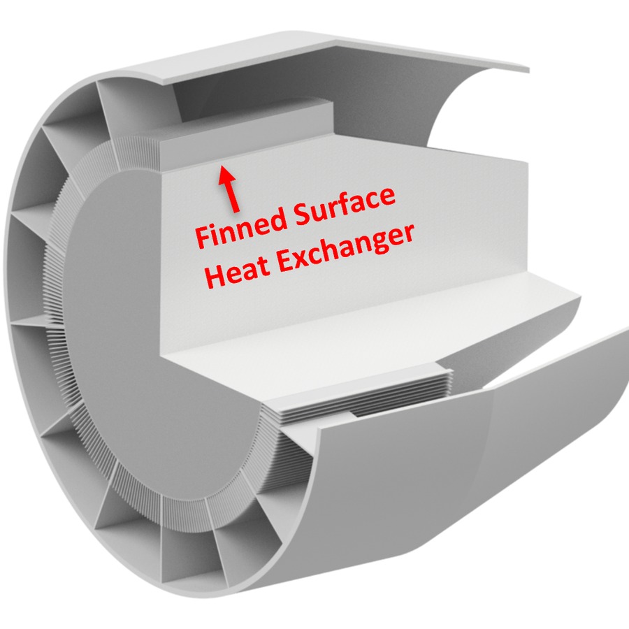
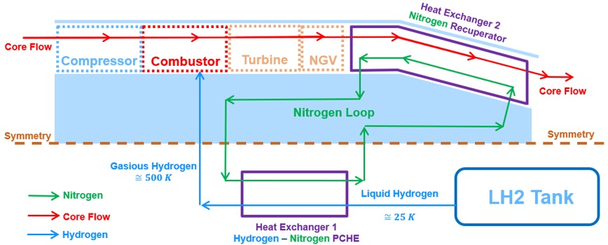
A sized, first-principles thermal management architecture for a liquid hydrogen jet engine, with heat exchanger mass and pressure drop estimated across the full flight envelope — providing the sizing baseline that every later stage of the DPhil builds on.
Identifying the heat exchanger recovering heat into the cryogenic hydrogen fuel stream as the most novel and highest-value component in the architecture set the direction for the rest of the DPhil: the remaining stages take this one heat exchanger from a sized concept through to experimental validation and design optimisation.