Can a single-stage gear pair be designed to transmit 95kW at 5000 RPM with minimum mass and volume, while remaining quiet, reliable, and manufacturable — meeting a specified 12,000-hour service life?
Every kilogram of unnecessary gearbox mass in an electric vehicle directly reduces range and increases unsprung/drivetrain weight. But minimising mass isn't free — it trades off against noise, vibration, harshness (NVH), manufacturing cost, and fatigue life. Getting this trade-off right, using rigorous stress analysis rather than rules of thumb, is exactly the kind of design discipline that separates a gearbox that survives its rated life from one that doesn't.
- Designed the gear pair's macro-geometry (tooth numbers, module, facewidth, helix angle) iteratively in Dontyne Systems' professional Gear Production Suite, balancing mass against ISO 6336 contact and bending stress safety factors
- Chose a prime pinion tooth number (31) to minimise hunting-tooth frequency, and a helix angle giving an integer overlap ratio of 2 for quiet running
- Specified micro-geometry modifications — tip relief, helix crowning, end relief — to minimise transmission error (TE), the direct driver of gear noise and vibration
- Ran tooth contact analysis (TCA) to simulate the real contact stress distribution across the tooth flank under load
- Accounted for real-world misalignment sources — manufacturing tolerance, gearbox case tolerance, and load-induced shaft deflection — rather than assuming perfect alignment
- Selected material (20MoCr4 case-hardened steel) and manufacturing route (hobbed, carburised, induction hardened, superfinished) to meet the required hardness and fatigue strength
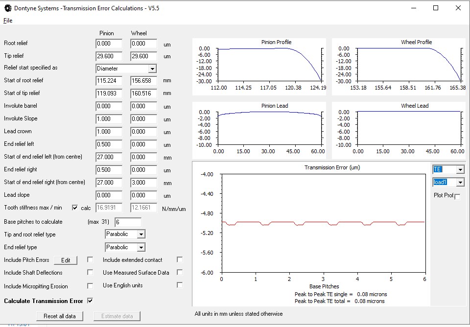
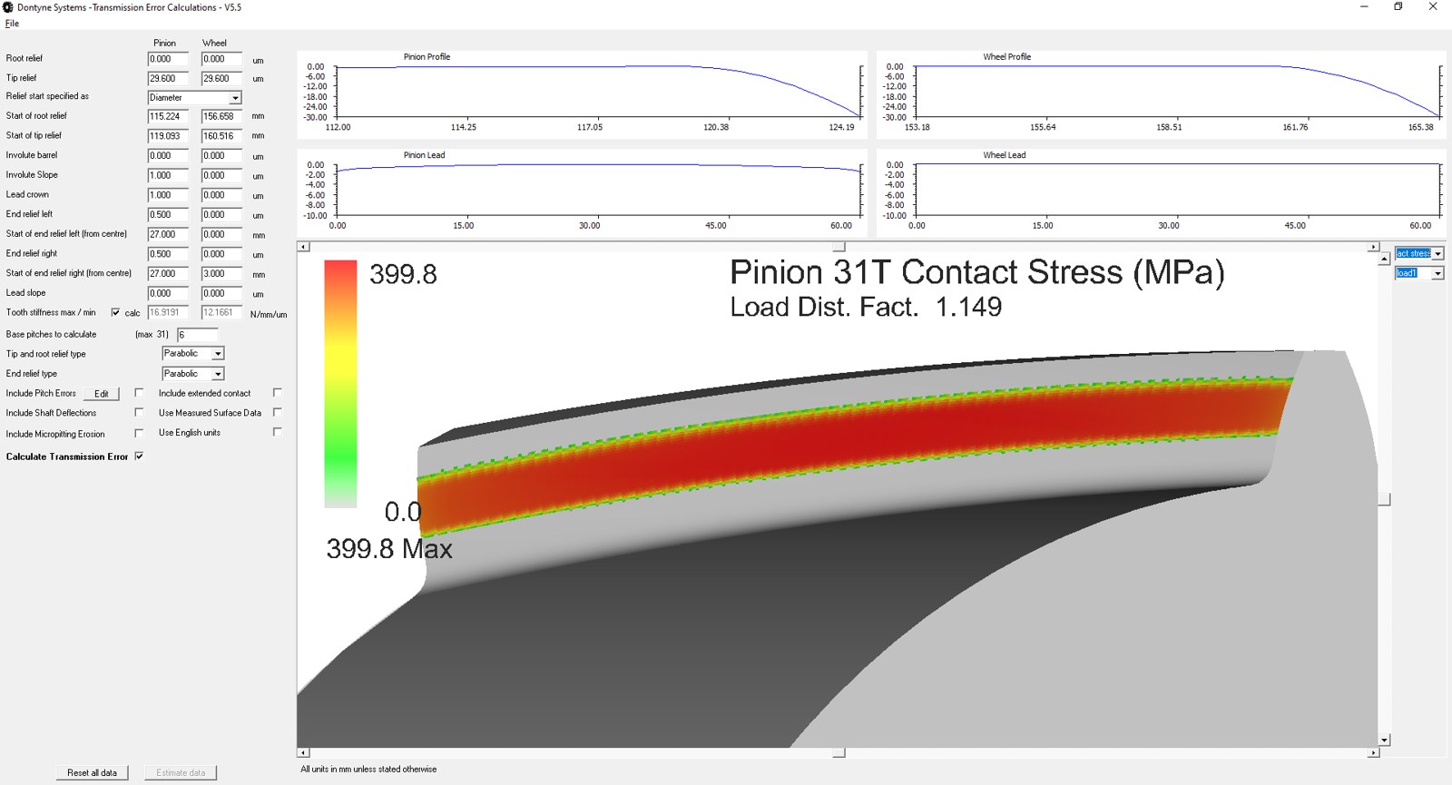
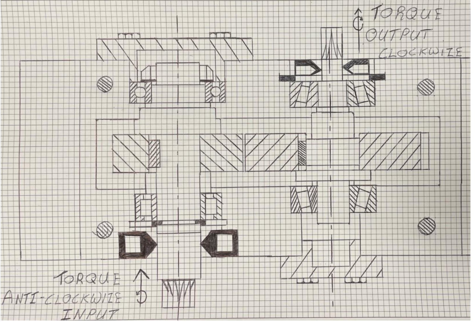
The final design achieved a total gear pair mass of just 14.3kg while sustaining the full 95kW rating, with contact stress safety factors of 1.24–1.25 and bending safety factors of 3.50 — both comfortably above the minimum of 1.0, even after accounting for manufacturing misalignment, shaft deflection, and dynamic loading.
Being honest about a design's remaining weaknesses is as important as reporting its strengths: the bending safety factor (3.50) came out considerably higher than needed relative to the contact factor (1.24), meaning some further mass could likely be trimmed with a different material or geometry choice — and the gear pair's resonance ratio (0.70) sits close enough to a known problem region to flag for further vibration analysis before this design would be production-ready. Identifying exactly where a design falls short, and why, is what turns a single analysis into a design that can actually be iterated on.