Which physical design parameters of a railway bogie most affect passenger ride comfort and vehicle stability, and what combination of parameters optimises both simultaneously?
Railway tracks are never perfectly straight or level, so a bogie's wheelsets constantly bounce, lurch, roll, pitch and yaw as they travel. Left unmanaged, this either produces an uncomfortable ride (through sharp jerks and accelerations felt by passengers) or, in the worst case, enough lateral and angular wheelset displacement to derail the vehicle entirely. Quantifying that trade-off precisely — rather than relying on rules of thumb — is what allows a bogie to be genuinely optimised rather than just "good enough."
- Built a MATLAB simulation of a bogie and its front/back wheelsets travelling down a poor-quality length of track, tracking their full spatial trajectory over time
- Derived a comfort factor from the resultant jerk and acceleration experienced by a passenger, weighted 10:1 in favour of jerk since it has the larger effect on perceived comfort
- Derived a stability factor from the maximum transverse and angular displacement between the two wheelsets, with a hard "derailed" condition if either limit was exceeded
- Ran a 3-round iterative optimisation across 5 parameters (cross-bracing stiffness, wheel stiffness, wheel diameter, wheelbase, wheel conicity), narrowing the search range and increasing resolution each round
- Repeated the full analysis on two vehicles of very different mass — a light theoretical bogie and the heavier Stadler WINK passenger train — to test whether the optimum parameters generalised
A large part of this project was reducing every input parameter's effect down to just two normalised performance metrics, each scaled to a 0–1 range:
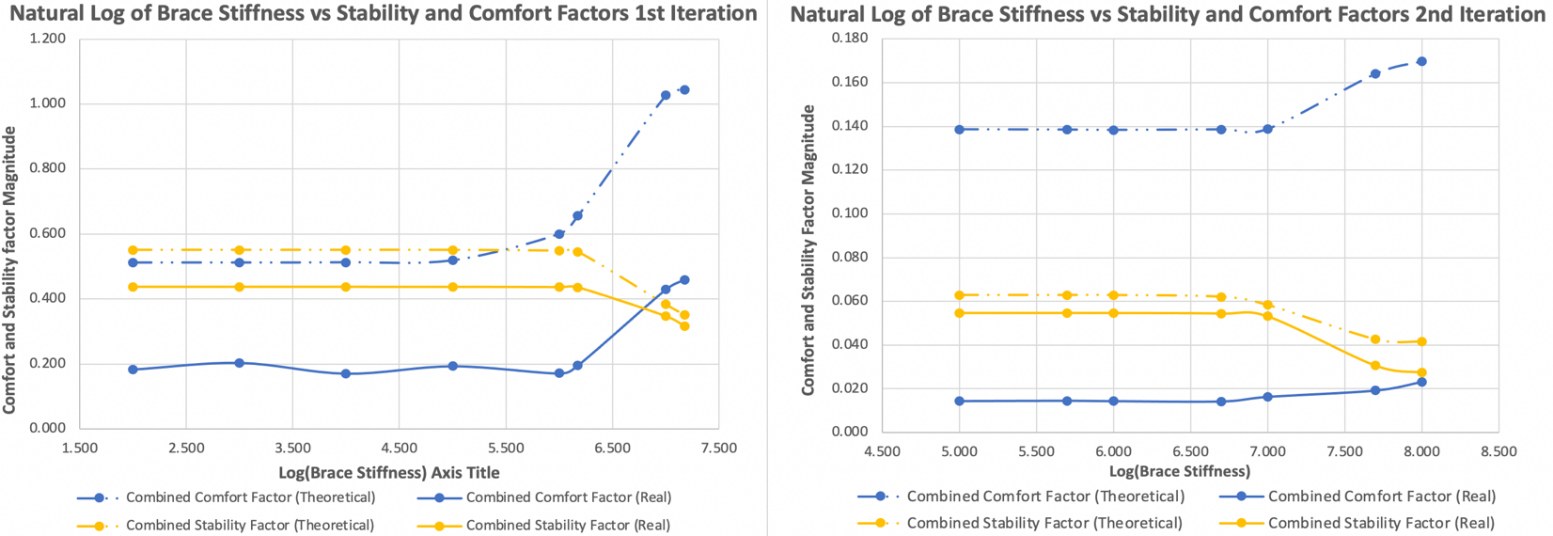
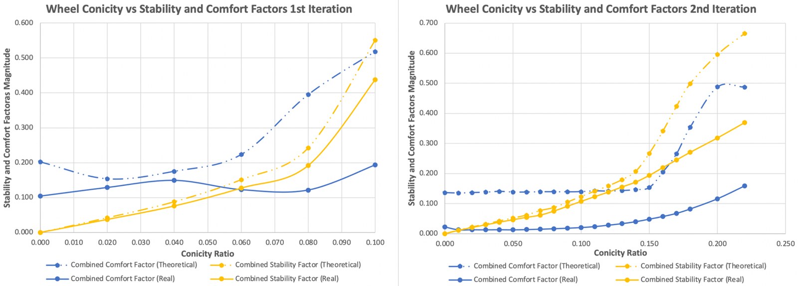
Applying the optimised parameters improved the light theoretical bogie's ride comfort by 3,942% and stability by 2,678%; the heavier Stadler WINK-based vehicle improved by 278% (comfort) and 876% (stability) — confirming the method generalises across vehicle mass, even though the optimal parameter values themselves differ.
Reducing a genuinely multi-physics ride-quality problem down to two clean, normalised, comparable metrics — then optimising against both simultaneously across two very different vehicles — is the same systematic design-space exploration approach used throughout the DPhil's heat exchanger geometry optimisation, just applied to a different physical system.