Can an FEA-optimised crane hook — validated against hand calculations — be manufactured and physically proven to safely carry a 30kN load without yielding, at minimum mass?
Lifting equipment is safety-critical: a crane hook must reliably carry its rated load without yielding, while minimising mass and material cost. This project follows the same design-verification loop used in real structural certification work — simulate, validate the simulation independently, manufacture, then physically test to confirm the prediction — rather than trusting a single FEA result in isolation.
- Validated the ANSYS Workbench FEA methodology against hand calculations on a known test specimen before trusting it on the real design
- Designed the hook geometry in Autodesk Inventor, to a fixed spec: withstand a 30kN static load without yielding, fit specified bolt/pin mounts, minimum mass
- Iterated through 7 design variants in ANSYS Workbench, tracking yield-load-to-mass ratio at each step to converge on an optimised geometry
- Cross-checked the final design's predicted stress against independent hand calculations using stress-concentration factors
- Had the final design laser-cut from 8mm Strenx 700MC high-strength steel
- Physically tested the manufactured hook to destruction and reconciled the real result against the FEA prediction
The first four design iterations, each refining geometry based on the previous round's stress distribution and yield-load-to-mass ratio:
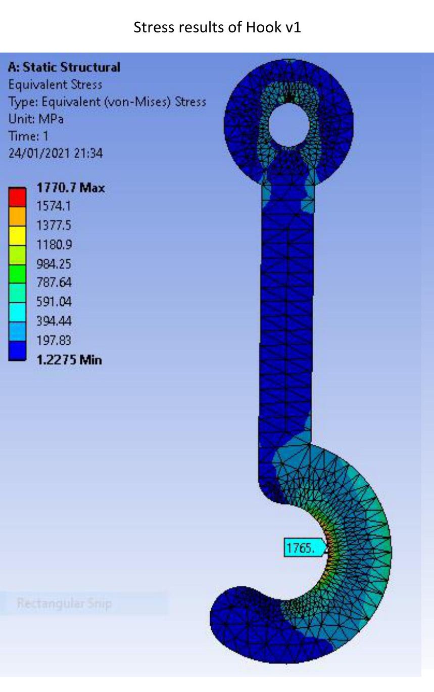
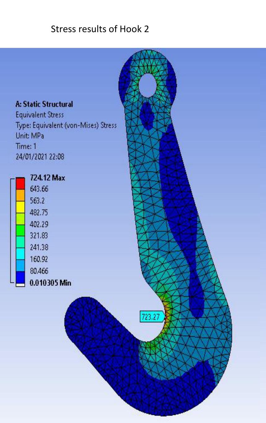
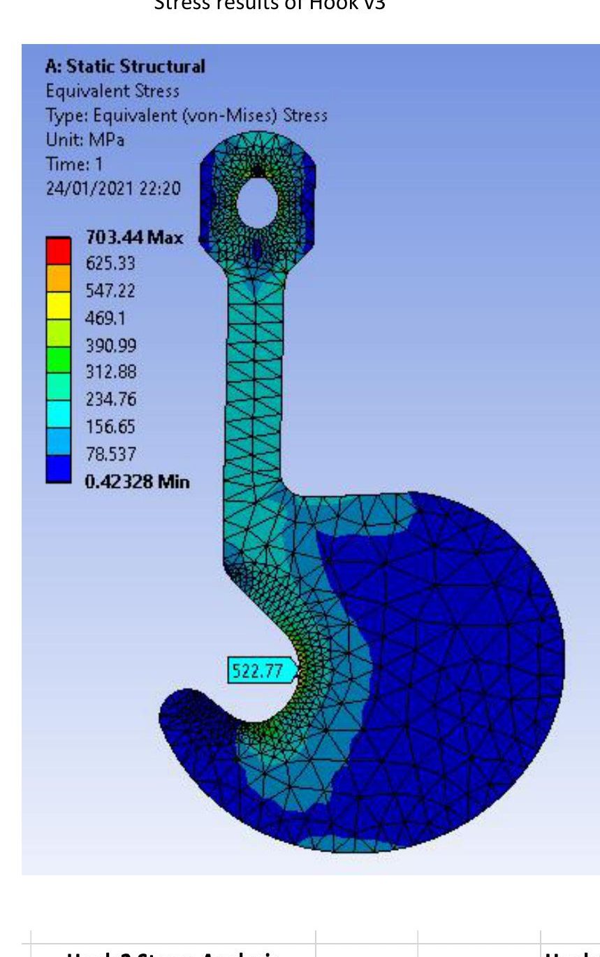
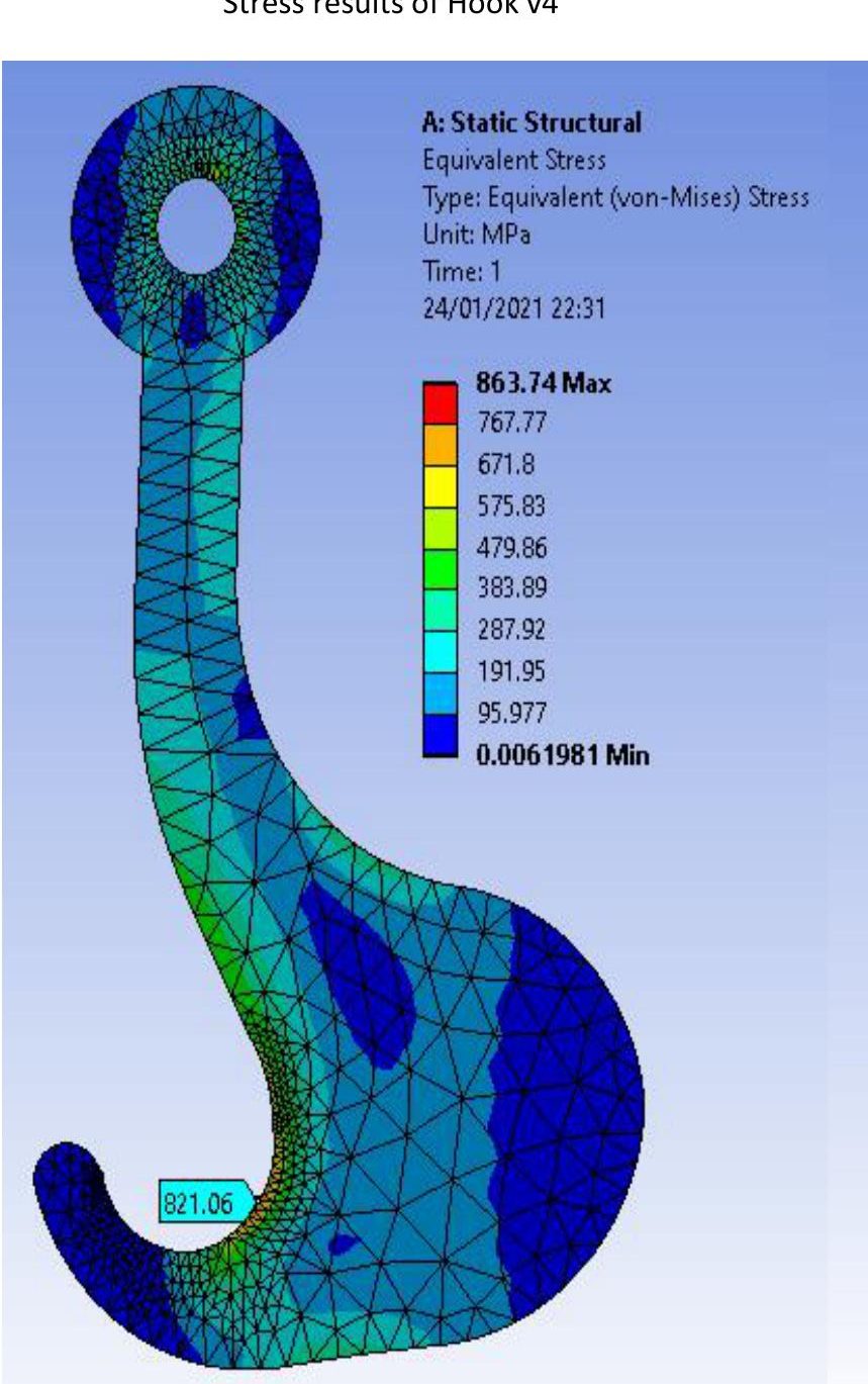
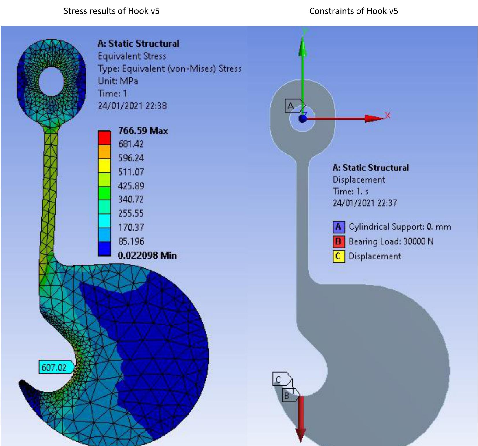
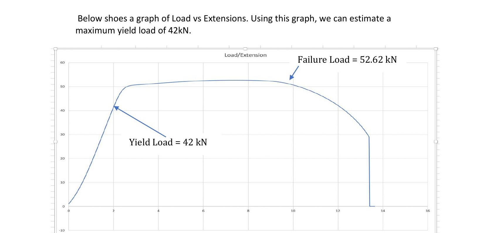
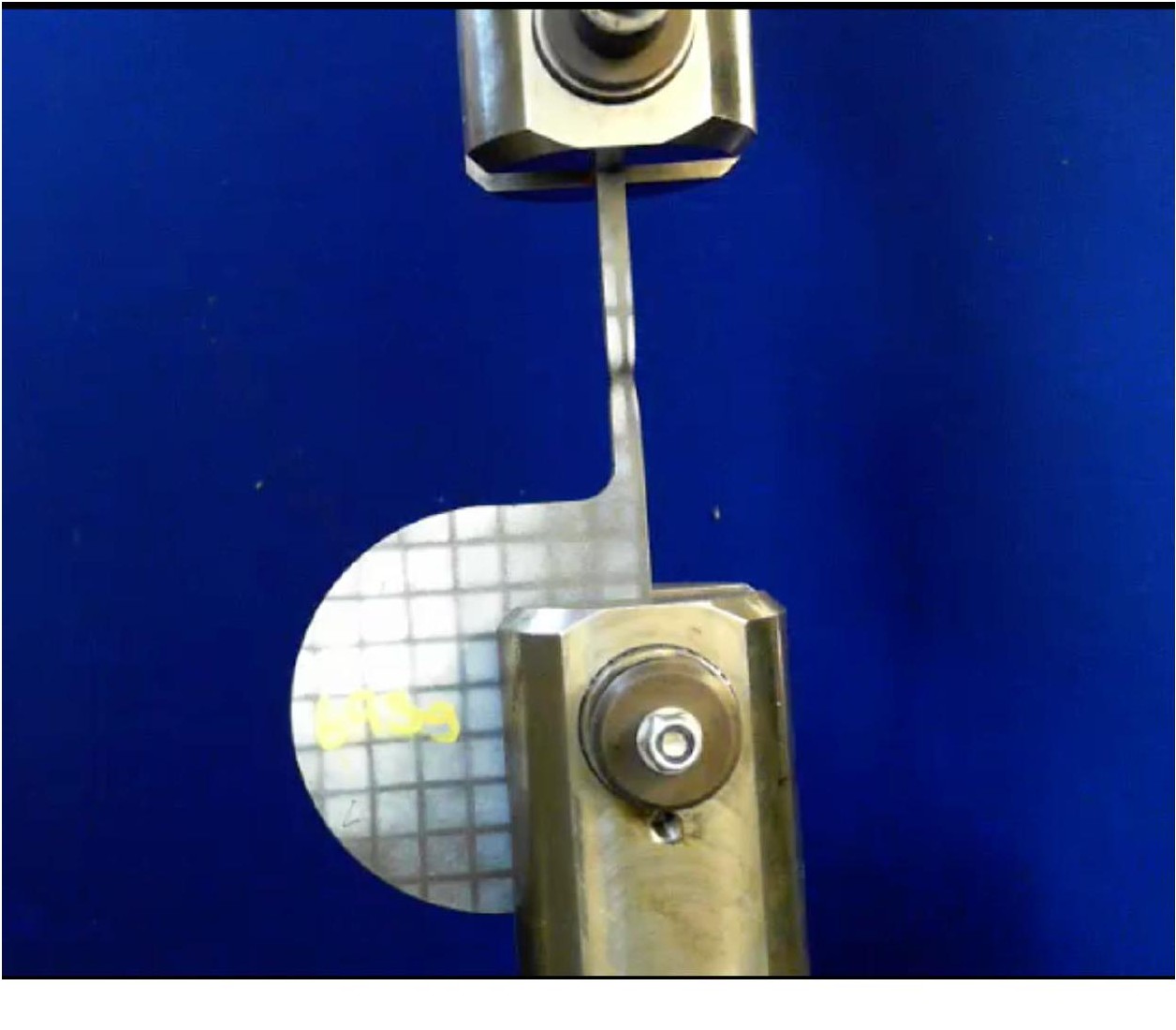
FEA predicted a yield load of 34.6kN at 700g; the physically tested hook yielded at ~32.9–42kN (depending on method used) and failed at 52.62kN — within single-digit percent of the FEA prediction, and comfortably exceeding the 30kN design requirement.
Beyond meeting the spec, the project's real value was in the reconciliation step: rather than treating the ~5% FEA-vs-test discrepancy as noise, I traced it to a specific, quantified cause — the yield stress assumed in ANSYS (700MPa) versus the steel's actual observed yield stress (660MPa) — and distinguished it from the far larger error introduced by simplified hand-calculation assumptions (over 200% discrepancy, due to modelling the hook as a two-notch flat plate rather than its true single-notch geometry). That habit of quantifying and explaining every source of error, rather than just reporting a result, is the same discipline this DPhil's CFD-vs-experiment validation work relies on.