Can an Arduino-based control system, using ultrasonic distance sensing and closed-loop PID feedback, autonomously detect obstacles and regulate a vehicle's motor speed to avoid collision?
Modern automotive Advanced Driver Assistance Systems (ADAS) — autonomous emergency braking, adaptive cruise control — are built on exactly this architecture: a ranging sensor feeds a closed-loop controller that continuously adjusts actuation in real time. Building a simplified version from scratch, at the level of individual sensor calibration and controller tuning, is a direct, hands-on route into how those production systems actually work under the hood.
- Designed and simulated a 4-ultrasonic-sensor "Safe Car" circuit in Tinkercad, built around an Arduino Uno
- Implemented and tuned a closed-loop PID DC motor speed controller with encoder feedback (Kp = 0.78, Kd = 19.5, Ki = 0.0078), validated independently as its own exercise
- Designed a serial communication protocol to stream front/back/left/right distance, light level, motor speed, and steering angle from the Arduino to a LabVIEW dashboard for live visualisation
- Investigated and calibrated a magnetometer for heading/orientation sensing, characterising its noise characteristics
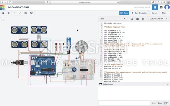
The simulated vehicle successfully detected obstacles via ultrasonic ranging and responded in real time. Full closed-loop PID control was validated separately on the motor speed-control exercise, but had to be disabled in the browser-based Tinkercad simulation itself — its physics engine couldn't run the control loop fast enough in real time, a practical lesson in simulation-platform limitations rather than the control theory.
The core loop practiced here — measure, compute an error signal, actuate, repeat — is the same closed-loop control principle used throughout engineering, including the PID-controlled heater surface temperature system built for the DPhil's experimental wind tunnel. It also gave an early, practical grounding in sensor calibration and multi-system serial communication that carried directly into later instrumentation work.